Mazda Tribute Lx Fuse And Relay Diagram
Mazda Tribute SUV has been produced since 2000 in two generations. 1st generation was produced in 2001, 2002, 2003, 2004, 2005, 2006. The 2nd generation was assembled in 2007, 2008, 2009, 2010 and 2011. During this time, the model has been restyled. In this publication you will find a designation of the Mazda Tribute fuses and relays with box diagrams and their locations. Let's highlight the fuse responsible for the cigarette lighter.

The locations of the boxes, the design and purpose of the elements in them may differ from that shown and depends on the year of manufacture, the region of delivery and the level of electrical equipment. Check your diagrams.
Contents
- 1 Passenger compartment fuse box
- 1.1 Type 1
- 1.2 Type 2
- 1.3 Relay
- 2 Engine compartment fuse box
- 2.1 Type 1
- 2.2 Type 2
- 2.3 Type 3
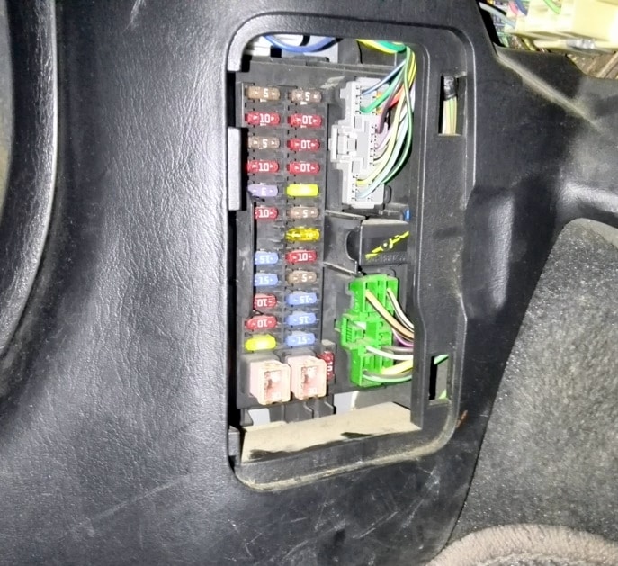
Passenger compartment fuse box
It is located under the dashboard (lower part of the instrument panel), on the passenger side and is covered by a protective cover. To access, simply pry with a flat screwdriver by the special notch in the cover.

Type 1
For example
Diagram

Assignment
| 1 | 5A Electro – pneumatic valve for the fuel vapor accumulator |
| 2 | 5A Fan relay, heated rear window |
| 3 | 10A Rear door glass wiper and washer motor |
| 4 | 10A 4WD control unit, instrument cluster |
| 5 | 5A ABS and SRS control unit |
| 6 | 10A Hazard warning lights, reversing lights |
| 7 | 10A Transponder signal amplifier, SRS control unit |
| 8 | 10A Instrument cluster, selector lock relay |
| 9 | 3A Relay for engine control unit and automatic transmission, fan relay, air conditioning relay |
| 10 | 20A Windshield wiper motor, windshield washer motor, intermittent wiper relay |
| 11 | 10A Starter relay, ignition key lock solenoid valve |
| 12 | 5A Radio and clock |
| 13 | Reserve |
| 14 | 20A Cigarette lighter |
| 15 | 15A Dimensions, spotlights, trailer wiring relay |
| 16 | 10A Instrument panel, power mirrors, electrical control unit |
| 17 | 15A Luke |
| 18 | 5A Illumination of the instrument cluster and instrument panel switches |
| 19 | 10A Subwoofer |
| 20 | 15A Direction indicators, turn signal indicators, hazard warning lights |
| 21 | 10A Trailer side lights |
| 22 | 15A Reserve |
| 23 | 15 / 20A Buzzer |
| 24 | 15A Brake lights, ABS control unit, engine and automatic transmission control unit, automatic transmission shift solenoid valves |
| 25 | 30A Power windows |
| 26 | 30A Central locking, ECM, power seats |
| 27 | 10A Radio, instrument cluster, interior lighting |
| ACC | Relay for additional equipment installation |
The fuse number 14, 20A, is responsible for the cigarette lighter.
Type 2
The photo

Diagram

Designation
| 1 | 15A Trailer lamps |
| 2 | 5A Radio (backlight) |
| 3 | 15A Front and rear parking lights |
| 4 | 10A Ignition switch |
| 5 | 2A Automatic transmission control unit relay, fuel pump relay, fan relay, No. 2 high / low fan speed |
| 6 | 15A Additional brake lights, brake lights, engine and automatic transmission control unit, ABS, cruise control |
| 7 | 10A Instrument cluster, OBD, radio, electric side mirrors |
| 8 | 15A Fog lights |
| 9 | 30A Central locking, power seats |
| 10 | 15A Heated side mirrors |
| 11 | 15A Luke |
| 12 | 15A Radio |
| 13 | Reserve |
| 14 | Reserve |
| 15 | 30A Power window drive |
| 16 | 15A Subwoofer |
| 17 | 15A Low beam |
| 18 | 18A AWD system |
| 19 | 15A Anti-theft system |
| 20 | 20A Buzzer |
| 21 | 10A Rear door glass wiper and washer motor |
| 22 | 10A Interior rearview mirror, instrument cluster |
| 23 | 5A Radio (power) |
| 24 | 20A Cigarette lighter |
| 25 | 20A Windshield washer and wiper motor |
| 26 | 5A Air Conditioner |
| 27 | 5A Cruise control switch |
| 28 | 10A Instrument cluster |
| 29 | 10A Reversing lights |
| 30 | Reserve |
| 31 | Reserve |
| 32 | 10A Selector lock relay |
| 33 | 15A SRS control unit, front passenger airbag deactivation indicator, front passenger seat sensor |
| 34 | 5A ABS unit, cruise control |
| 35 | 5A Heated seats, four-wheel drive |
For the front cigarette lighter fuse number 24, 20A is responsible.
Relay

On the back of the unit there may be some relays, such as:
- Anti-pinch relay
- Starter relay
- Relay dimensions
- Horn relay
Engine compartment fuse box
It is located on the left side, next to the battery, under the protective cover. On the reverse side of which the actual assignment of fuses and relays will be applied.

Type 1

legend

Functions
| Horn | 15A Sound signal |
| H / LLH | 15A Left headlight |
| H / L RH | 15A Right headlight |
| EEC | 5A Engine management system |
| SOUTH | 15A Fuel injection system |
| FUEL | 20A Fuel pump |
| DIODE | Diode |
| DIODE | Diode |
| H/L RELAY MICRO | Headlight relay |
| INJ | 30A Engine management system, MAF sensor, idle speed control valve |
| MAIN | 120A Main fuse |
| EVERYTHING | 15A Generator |
| (DRL) | 15A Daytime lighting system |
| (DRLZ) | 15A Daytime lighting control unit |
| (HLEV) | 10A Headlight range control |
| PWR1 | 15A Socket for connecting additional devices |
| FOG | 20A Fog lights |
| A/C | 15A Air Conditioning Compressor Clutch |
| (SECTION) | 25A Anti lock brake system |
| PWR2 | 15A Socket for connecting additional devices |
| IG MAIN | 40A Starter chain |
| HTR | 40A Fan motor, fan motor relay |
| BTN 1 | 40A Radio tape recorder, cigarette lighter, instrument cluster, electric mirrors |
| (SECTION) | 60A ABS pump motor |
| BTN 2 | 40A Radio tape recorder, instrument cluster, "cruise control", electric seat adjustment, sound signal |
| MAIN FAN | 40 / 50A Main fan |
| RDEF | 30A Heated rear door glass |
| ADD FAN | 40 / 50A Additional fan |
| EEC MAIN ISO | Engine control relay |
| FUEL PUMP ISO | Fuel pump relay |
| MAIN FAN ISO | Low fan speed relay (YF motor) High fan speed relay # 1 (AJ motor) |
| ADD FAN ISO | High fan speed relay (YF motor) Low fan speed relay (AJ motor) |
| DEF RELAY ISO | Rear door glass heater relay |
| ST RELAY ISO | Starter relay |
| ADD FAN 2 ISO | Relay # 2 high fan speed (motor AJ) Relay for middle fan speed (YF motor) |
| FOG RELAY MICRO | Fog lamp relay |
| A/C RELAY MICRO | A / C Compressor Clutch Relay |
Type 2

Diagram

Description of the circuit
| 1 | 25A Instrument panel fuse |
| 2 | 25A Headlights |
| 3 | 25A High beam headlights, direction indicators, interior lighting, headlights |
| 4 | 5A Delay system for turning off the power of some circuits after turning off the ignition |
| 5 | 15A Oxygen sensor heater |
| 6 | 20A Gasoline pump |
| 7 | 40A RUN / ACC Relay – Cigarette Lighter, Windshield and Tailgate Wipers |
| 8 | 30A Engine and automatic transmission control unit, injectors and coils |
| 9 | 15A Generator |
| 10 | 30A Heated seats |
| 11 | 10A Engine and automatic transmission control unit |
| 12 | 20A Sockets for connecting additional equipment |
| 13 | 20A Fog lights (headlights / lights) |
| 14 | 15A A / C Compressor Electromagnetic Clutch, A / C Relay |
| 15 | 30A Anti lock brake system |
| 16* | 25A Instrument panel fuse |
| 17 | 50A Starter circuit |
| 18 | 40A Fan motor |
| 19 | 40A Auxiliary relay – subwoofer, AWD system, low beam headlights |
| 20 | 60A Anti lock brake system |
| 21 | 40A Horn, auxiliary brake light, instrument cluster, central locking and power seats |
| 22 | 40 / 50A Radiator Fan |
| 23 | 40A Heated rear door glass, parking light relay |
| 24 | 40 / 50A High / low speed fan |
| 25 | Shunt |
| R2 | Relay for engine and automatic transmission control unit |
| R3 | Fuel pump relay |
| R4 | Radiator fan relay |
| R5 | Relay # 1 high / low fan speed |
| R7 | Starter relay |
| R8 | Relay # 2 high / low fan speed |
| R9 | Fog lamp relay (headlights / lamps) |
| R10 | Air conditioner relay |
| D1 | Starter diode |
| D2 | Air conditioner diode |
Type 3
Photo for example

Diagram

Appointment
| A | 80A Electronic Power Steering (EPAS) Module |
| B | 125A Passenger compartment fuse panel |
| 1 | 15A Heated mirror |
| 2 | 30A Rear heater |
| 3 | 20A Rear sockets (center console) |
| 4 | Reserve |
| 5 | 10A Powertrain Control Module (PCM) – Supports Power, PCM Relay, Canister Vent |
| 6 | 15A Generator |
| 7 | 15A Luke |
| 8 | 20A Trailer parking lights |
| 9 | 50A Anti lock brake system (ABS) |
| 10 | 30A Front wipers |
| 11 | 30A Starter |
| 12 | 40A Fan motor |
| 13 | 10A Air conditioner clutch |
| 14 | 15A Trailer headlights |
| 15 | Reserve |
| 16 | 40A Cooling fan 1 |
| 17 | 40A Cooling fan 2 |
| 18 | 20А ABS |
| 19 | 30A Power Seats |
| 20 | A / C drive relay |
| 21A | Rear defogger relay |
| 21B | Fuel relay |
| 21C | Fan relay |
| 21D | PCM relay |
| 22 | 20A Fuel pump |
| 23 | 15A Fuel injectors |
| 24 | Not used |
| 25 | 5А ABS |
| 26 | 15A Ignition coils |
| 27 | 10A Power Train Component Malfunction Indicator Lamp |
| 28 | 20A Power Train Component Malfunction Indicator Lamp |
| 29 | 15А PCM |
| 30A | Cooling fan relay 1 |
| 30B | Starter relay |
| 30C | Cooling Fan Main Relay |
| 30D | Cooling fan relay 2 |
| 31A | Tail light relay |
| 31B | Not used |
| 31C | Left Turn Trailer Relay |
| 31D | Trailer Right Turn Relay |
| 31E | Trailer |
| 31F | Lock relay |
| 32 | Not used |
| 33 | Air conditioner diode |
| 34 | Starter diode |
| 35 | Strat / stop, reversing lights, rear heater relay |
| 36 | Reserve |
If you know how to make the material better or if you have something to push, write everything in the comments.
Posted by: altonexproningoap.blogspot.com
Source: https://fuseandrelay.com/mazda/tribute.html

Posting Komentar untuk "Mazda Tribute Lx Fuse And Relay Diagram"